


Strain rate control on a universal testing machine changes your tensile result more than most labs expect. Run the same specimen under two control modes and you can get two different yield numbers, because the material feels the difference between a slow pull and a fast one. That single fact is why standards spend pages on rate, and why a machine that cannot hold a rate cannot claim to follow a method.
This guide follows the order a metrologist actually thinks in, not the order a datasheet is written. We will cover five things in sequence: the three control modes and how they differ, why rate physically changes the result, how sensitive metals, polymers and composites really are, what ASTM, ISO and GB actually specify, and the equipment figures that let you prove you held the rate. We start with control, because everything else follows from it.
The short version, if you only read this far
- Three modes exist — constant crosshead speed, constant stress rate and constant strain rate — and they give three different curves.
- Rate changes the yield point, the modulus you read on a polymer, and how much the specimen self heats.
- Metals, polymers and composites have very different sensitivity, so one rate does not fit all.
- ASTM, ISO and GB describe rate differently, and comparisons only work when the control mode matches.
- Closed loop control, not a fixed speed, is what proves you held the rate.
Step 1: Tell Apart the Three Control Modes on a Universal Testing Machine
Three control modes look similar on a screen and behave completely differently on a specimen. The first holds the crosshead at a fixed speed; the second holds the rate at which stress rises; the third holds the rate at which strain rises. They sound like three ways to say the same thing. They are not, and the difference becomes obvious the moment the specimen stops behaving like a spring.
| Control mode | What it really holds | Where it misleads you |
|---|---|---|
| Constant crosshead speed | The grip travel per minute | Actual strain rate drifts as the specimen stiffens or yields |
| Constant stress rate | How fast the load climbs per second | Crosshead speed changes constantly, so you must log it |
| Constant strain rate | The deformation rate measured on the specimen itself | Needs a real extensometer and true closed loop control |
The practical point is the middle column. A machine told to move at a fixed speed is only holding the grips steady, not the material. As the specimen yields, the same grip speed produces a very different strain rate inside the gauge length. That is why a modern specification often asks for the third mode and the measurement that supports it. With the modes separated, the next question is why the rate matters at all.
Step 2: Understand Why Rate Physically Changes the Result
Rate changes the result for four separate reasons, and it is worth naming them because they do not all point the same way. When two labs disagree about a tensile number, the cause is usually one of these four, not a fault in the machine.
- Yield behaviour is rate dependent. Many metals show an upper and lower yield point, and how sharply they separate depends on how fast you load them. A faster pull tends to raise the apparent yield stress, so a rate change moves the number you report.
- Polymers are viscoelastic. Their response contains a time term, so a faster test makes them look stiffer and a slower test makes them look softer. The modulus of a polymer is only meaningful next to the rate it was measured at.
- Local heating grows with rate. Pull a specimen fast and the deformation heat has less time to escape, so the gauge section warms and the material softens. Fast tests can read lower than slow ones for this reason alone, which is why the high rate case is not simply stiffer.
- Strain rate sensitivity varies with the material. The rate sensitivity index describes how much flow stress rises with speed, and it is small for some alloys and large for many plastics, so the same rate change can be invisible on one material and obvious on another.
Two of those effects push the strength up and one pulls it down, which is exactly why you cannot guess the direction of a rate error. You have to control the rate and record it. Now that you know why it matters, the next question is how much it matters for the material in front of you.
Step 3: Judge the Sensitivity of Your Material
Sensitivity to rate is a property of the material, and the three families behave so differently that one rate policy cannot cover them. Treat this as a sorting exercise, not a specification.
| Material family | Sensitivity to rate | What it means for your test |
|---|---|---|
| Metals | Moderate, and stronger near the yield point | Hold the yield region rate carefully; the elastic region is more forgiving |
| Polymers | High, across the whole curve | Report the rate with every modulus value, or the number means little |
| Composites | Mixed, and strongly orientation dependent | Keep fibre direction and rate fixed together between batches |
For metals, the region that matters most is the one around yield, so that is where control has to be tightest. For polymers, the whole curve moves with rate, so the rate belongs next to every reported value. For composites, the fibre direction and the rate have to be held together, because changing one without the other makes two batches incomparable. Once you know your material's sensitivity, the last external input is what the standards actually ask for.
Step 4: Read What the Standards Really Specify About Rate
The three main families describe rate in three different ways, and the difference is not cosmetic. ASTM metal tensile methods have traditionally given a stress rate for the elastic region and a strain rate band around yield, with a crosshead speed afterward. ISO metal methods split the same job into two routes, one built on closed loop strain rate control and one built on stress rate or crosshead speed, and the choice of route changes the paperwork you keep. GB follows the ISO structure closely, so a lab working to both can usually run one routine.
Take one document at a time and it stays simple. The reason rate gets so much attention is that a single clause in it decides whether two results can be compared at all. Here is the rule that matters more than any single number:
- Inside one comparison, use one control mode. Mixing a crosshead speed run with a closed loop strain rate run in the same table is the fastest way to create a difference that is not real.
- Record the mode, not just the number. A result without its control mode is an incomplete record, even if the value looks right.
- When a customer method points at ASTM, ISO or GB, check which route that document allows before you set the software, because the route decides what you log.
If your plan spans more than one family, take the strictest rate requirement and hold that everywhere. It costs nothing extra once the machine can do it, and it removes the reconciliation later. That raises the final question: what does the machine itself have to deliver?
Step 5: Check the Equipment Figures That Prove You Held the Rate
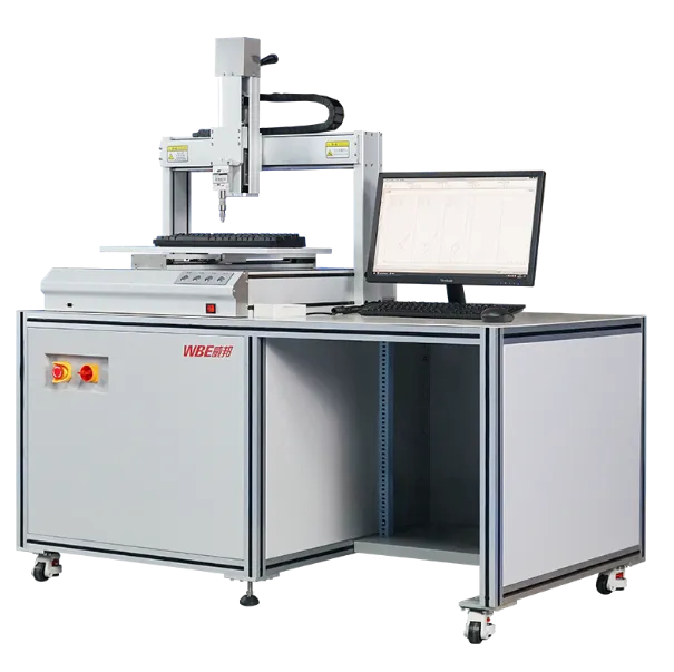
A machine holds a rate only if it can measure the specimen and change its own speed in response, thousands of times a second. That is closed loop control, and it is the difference between a frame that can move at a set speed and one that can hold a set strain rate. Here are the figures we publish and commission against on the WBE-9809 series, so you can hold a supplier to them:
| Figure | Model B, Level 0.5 | Model A, Level 1 |
|---|---|---|
| Strain rate control range | 0.02 to 5% FS/s | 0.05 to 5% FS/s |
| Strain rate relative error | ±2% below 0.05% FS/s, ±0.5% at or above it | Same error class applied to the narrower range |
| Force control rate | 0.005 to 5% FS/s | 0.01 to 5% FS/s |
| Beam speed accuracy | ±1.0% below 0.01 mm/min, ±0.2% at or above it | Same accuracy class |
| Displacement resolution | 0.015 µm | 0.001 mm |
| Control loop | Closed loop across displacement, speed and load | Closed loop across displacement, speed and load |
Two of those lines do the real work. The strain rate relative error is the number that tells you how well the machine holds the rate you set, and the two tier figure above shows why the low rate range is the harder one: below a small threshold the tolerance relaxes, because holding a very slow rate is genuinely difficult. The closed loop line is the mechanism. A 32 bit ARM control board reads the encoder, which on these frames is a LINE 2500 r/p photo electric unit, and adjusts the Panasonic servo many times a second, so when the specimen starts to yield the crosshead speed changes to keep the strain rate where you set it. Without that loop, the machine only ever holds a speed, and the number on your certificate is an assumption rather than a measurement.
The same frame choices carry across the range. Force classes run at 100 kN, 300 kN and 600 kN so you can keep the coupon in the comfortable part of the scale, and every model is documented against GB, ISO, JIS, ASTM and DIN, which is what lets one routine answer several customers. If your work sits at the small end, a benchtop frame covers it with the same control figures, and electronic universal testing machine specifications list them model by model. For work that has to stay hot through the pull, the same control logic lives on an environmental tensile tester, and small specimens are handled on a small tensile testing machine.
For background on how these frames are built and where they sit in a lab, our guide to mechanical testing machines walks through the hardware, and the automotive programmes we support show how rate control is written into a customer method. WBE has built this equipment since 1995 from Dongguan, Guangdong, China, in our own 12,000+ square metre plant, and we hold ISO9001, ISO14001, CE, RoHS and CNAS. Standard models leave in 15 to 20 days.
Frequently Asked Questions
Does a universal testing machine need an extensometer for strain rate control?
For true strain rate control, yes. The machine has to know the deformation of the specimen, not the travel of the grips, and only an extensometer measures that directly. Some methods accept a stress rate or a crosshead speed instead, and those can run without one, but they are a different route to the same test.
Why is a slow rate harder to hold than a fast one?
Because the correction the machine must make becomes very small, and small corrections are harder to make smoothly. That is why published tolerances often relax below a low rate threshold. If your method runs at a very slow rate, check the machine can actually hold it rather than assume it can.
Can we compare results from a stress rate run with a strain rate run?
Only with great care, and usually not directly. The two modes hold different quantities, so a material that is rate sensitive will sit at a different point on its curve in each. For a genuine comparison, run both conditions in the same mode and change only the value.
How do we prove in an audit that the rate was held?
Keep the control mode, the target rate and the measured rate together in the run file, with the closed loop status visible. A graph of strain rate against time is far more convincing than a setpoint typed into a form, because it shows what the specimen actually experienced during the test.
Getting strain rate control right on a universal testing machine is not a software checkbox. It is the difference between reporting a number the specimen produced and reporting a number the crosshead produced, and standards compliance depends on knowing which one you have. Choose the mode deliberately, hold it in closed loop, log it with the result, and your tensile data will survive a comparison, a round robin and an audit without an argument.
Hold the rate your method demands
Tell us the standard and the material you test, and we will show you the frame and control figures that keep every run comparable.
Review testing machine specs Send us your test method