


A reliability testing equipment matrix is built backwards from how the product fails, not forwards from the machines you already own. Start with the failure mechanisms that actually retire the product in the field — corrosion, joint fatigue, connector wear, housing stress — and only then pick the test that reproduces each one. Everything else in this article follows from that single decision, and it is the decision most teams get wrong.
This guide follows the order a test plan is actually assembled, not the order a catalogue is laid out. We will cover five things in sequence: reading failure modes into test items, fixing the order of those tests, choosing sample size and cycle count, recognising the four signals of over-testing, and locking equipment and capacity into one matrix table. We will pick machines last, because the failure list decides the rig, never the other way round.
The short version, if you only read this far
- Test items come from failure mechanisms, not from an equipment list.
- Sequence changes the result: a thermal soak before vibration is a different test from the reverse.
- Sample size and cycle count are a confidence decision, written before the first unit fails.
- Over-testing kills good designs, and four signals tell you it is happening.
- One matrix table ties failure mode, test item, machine, sample size and verdict together.
Step 1: Read Failure Mechanisms Into Test Items
The first move is to stop thinking in test names and start thinking in failure mechanisms. A test name is a machine; a failure mechanism is a reason. When you start from the reason, the test list almost writes itself, and you stop buying machines for tests nobody asked for. Take a return, or a field failure, or a service claim, and ask one question: physically, what killed this part?
For an automotive electronics customer we worked with, the answer was not "heat". It was three separate mechanisms — electrochemical migration between connector pins, solder joint fatigue at a power device, and fretting wear on a board-to-board contact. Those three names point at three different tests, and only one of them is a pure temperature test. That is the shift from a device list to a failure list, and it removes about a third of the tests a catalogue would have suggested.
| Failure mechanism | How it shows in the field | Test item that reproduces it | Equipment class |
|---|---|---|---|
| Electrochemical migration | Leakage and short between adjacent pins | Biased damp heat, steady 85/85 | Temperature and humidity chamber |
| Solder joint fatigue | Cracking after seasonal temperature swings | Thermal cycling, thermal shock | Rapid change or shock chamber |
| Fretting wear | Rising contact resistance over vehicle life | Random vibration with load applied | Vibration table, combined system |
| Housing stress crack | Split at a screw boss after assembly | Mechanical load, insert pull force | Universal or torque testing machine |
| Conformal coat delamination | Moisture under the film, then corrosion | Humidity soak plus rapid transition | Humidity and rapid change chamber |
Notice that the last column is not the point. The point is the first two, because they come from the field and the field does not care what your lab owns. Once the failure mechanisms are written down and matched to a test item, the next question is the order you run them in.
Step 2: Fix the Sequence Before You Fix the Numbers
Sequence is not bookkeeping, it is part of the test. Environment first, then mechanics is a different experiment from mechanics first, then environment, and the two can disagree by a wide margin. The reason is simple. A humidity soak softens or swells a polymer, and the vibration that follows acts on a different material than the one you started with. Reverse the order and the vibration acts on dry material, then the humidity attacks an already-cracked joint. Same two machines, two different products.
When teams get a surprise, it is almost always a sequence surprise rather than a magnitude surprise. So write the order down as a decision, not as a default, and use three rules to make it:
- Match the order the product will live in. A part that ships through a humid port and then rides a truck should see humidity before vibration.
- Put the preconditioning step first. If humidity, salt or dust changes the material, run it early so the mechanical test sees the aged part.
- Keep one combined step for realistic exposure. Real assemblies meet heat and vibration at the same time, not in tidy blocks, which is why a combined temperature and vibration system earns its place.
A connector maker in Southeast Asia learned this the hard way. Their plan ran random vibration first and damp heat second, and every sample passed. They flipped the order, ran humidity before vibration, and a third of the samples failed at the same hour. The design was not changed. The sequence was. With the order locked, the next question is how many samples and how many cycles that order needs.
Step 3: Set Sample Size and Cycle Count From the Decision You Need
Sample size and cycle count are a confidence decision, and that decision has to be written before the first unit fails. If you set the rule after you see the data, you are not testing, you are negotiating with your own result. Most arguments about "the test was too harsh" are really arguments about a rule that was never fixed in advance.
- Decide what the test is for. A demonstration test proves a target the design already claims; a verification test is trying to break the design and find its weak point. The two need different sample counts and you should never mix them in one run.
- Size the sample to the question. A rough screening lot can be very small, while a life claim needs enough units that a single failure still leaves a defensible statement. More samples buy confidence, and confidence is what you are really ordering.
- Set the cycle count from the field, then add margin deliberately. Cycles should reflect the life you must survive, times a factor you can justify in writing, not a round number that felt safe.
- Write the accept and reject rule first. State how many failures stop the test, and what happens to the survivors. A rule that only appears after the run is not a rule.
When the numbers are chosen this way, they stop being arbitrary. The plan also becomes cheaper, because you stop running lifetime careers of cycles to answer a screening question. Now you know what you intend to run; the next step is watching for the signs that you have already gone too far.
Step 4: The Four Signals That You Are Over-Testing
Over-testing is more expensive than under-testing, and that is the part people resist. A missed defect ships once and gets caught later. A good design ruled bad gets re-engineered, re-tooled and re-qualified, and the cost lands on a product that was never broken. In our experience the second mistake burns far more engineering hours. Watch for four signals.
- Failures cluster right at the end of the run. Failures that appear only in the last few cycles are wear-out, not a defect escaping the design. That is your test talking about its own duration, not about the product.
- Every sample fails, including ones you have already validated. If a hundred percent of units fail a test that historically passed, suspect the test first, then the product.
- The test condition has no counterpart in the field. Testing far beyond any recorded service condition can be defensible as an accelerated screen, but only if you can name the acceleration you are assuming.
- Field returns do not corroborate the lab failure. When the lab fails parts that never fail in service, the lab is measuring its own setup, not the product.
Treat any one of these as a prompt to check the margin, not as proof the design is weak. Two of them together usually mean the test is the problem. Once you can see over-testing clearly, the last job is to write the whole plan into one table you can hand to the lab.
Step 5: Align Your Reliability Testing Equipment and Capacity in One Matrix Table
A good reliability testing equipment matrix fits on one page and answers five questions per row: which failure mechanism, which test item, which machine, how many samples, and what counts as a verdict. If a row cannot be filled, that row is not ready to run. Here is the template we hand to customers, filled with one realistic line:
| Failure mechanism | Test item | Equipment | Sample size | Verdict rule |
|---|---|---|---|---|
| Migration | 85/85 biased damp heat | Humidity chamber | 12 units | Zero leakage increase |
| Joint fatigue | Thermal shock, three slot | WBE-LR3 three slot | 8 units | Any crack stops the run |
| Fretting wear | Random vibration under load | Combined temperature and vibration | 6 units | Contact resistance drift |
| Housing stress | Insert pull force | Push pull tester | 10 units | Force below floor value |
That table is where capacity meets physics, and this is the part clients underestimate. It is easy to specify the right condition and impossible to run the planned sample count if the chamber volume is wrong. Most climate testing starts in a high and low temperature humidity test chamber, where the honest numbers are -40, -20 or -70 °C up to +150 °C across the A, B and D classes, humidity from 20% to 98% RH, uniformity within 1.5 °C and fluctuation within ±0.3 °C. Heating runs at 4 °C/min or faster and cooling at 1 °C/min or faster as averages, and those two figures decide how many cycles fit in a working week.
When the row calls for a faster ramp, a rapid change chamber rated at 5, 10, 15, 20 or 25 °C/min covers it, and it supports both linear and average modes, which matters because a linear ramp is a promise and an average ramp is a summary. For joint fatigue that needs the sharpest transition, the three slot thermal shock design keeps the samples still while air doors move the temperature, so modules with harnesses or bias wiring can travel with the load. Semiconductor plans that need accelerated moisture will usually add HAST, which covers the JESD22-A100 to A118 range, offers 4 to 128 bias terminals and stays compatible with PCT cooking, and our vibration testing range pairs the mechanical rows with either a WBE-SZH512L vibration test chamber or a full WBE-SZHKS rapid temperature and vibration test system when the exposure has to be simultaneous.
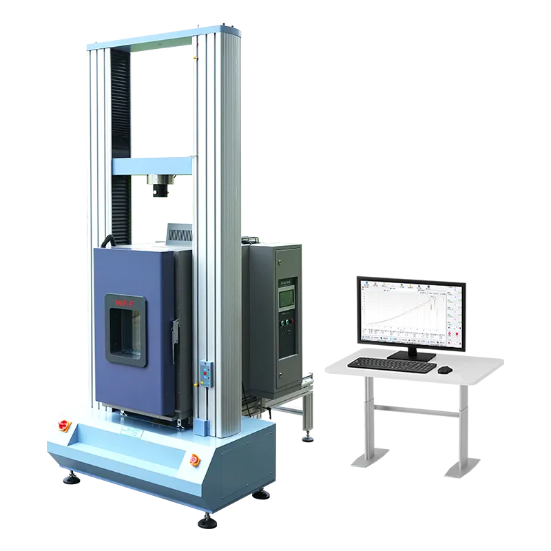
Mechanical rows lean on a universal testing machine at 100, 300 or 600 kN in Level 0.5 accuracy, and micro joints go to a WBE-9088B push pull tester that handles wire pull, ball shear, die shear, downforce and pullout in one frame. WBE has built this equipment since 1995 from Dongguan, Guangdong, China, in our own 12,000+ square metre plant, and we hold ISO9001, ISO14001, CE, RoHS and CNAS. Standard models leave in 15 to 20 days. Automotive teams usually anchor the whole matrix on one combined platform, which is why the automotive reliability programmes we support look more like a workflow than a shelf of machines.
Frequently Asked Questions
How many samples does reliability testing equipment really need per row?
There is no universal number, and anyone who quotes one is guessing about your decision. Screening rows can run on a very small lot, while a life claim needs enough units that a single failure still leaves a statement you can defend. Set the count from the question, then write the stop rule before you start.
Should temperature and vibration always run as one combined test?
No, but it should be a written choice rather than a default. Combined exposure is closer to the field and often finds issues that separate tests miss, yet it is slower and ties up one platform. Run it where the failure mechanism is genuinely simultaneous, and keep the separate rows for the rest.
Can I reuse one chamber for humidity and rapid change rows?
Often yes, if the ramp rate you need is modest and humidity is the only extra variable. The moment the plan needs a very fast transition or a thermal shock profile, a dedicated platform does the job better. Match the machine to the row, then look for sensible sharing across rows.
How do we keep a matrix alive after the first plan?
Treat it as a living document tied to field returns. Every failure that reaches you should either match a row or add one. A matrix that never changes is a matrix that has stopped listening to the field.
Building a reliability testing equipment matrix without over-testing comes down to one habit: let the failure mechanisms choose the tests, and let the tests choose the machines. Write the sequence, the sample count, the stop rule and the verdict down before anything runs, and the matrix becomes a document you can defend for years instead of a list of tests someone inherited. Teams that plan it this way spend less on hardware and argue less about results, because every row already explains why it exists.
Turn your failure list into a machine shortlist
Send us the failure mechanisms you need to cover and we will map them to the test items, volumes and sample counts that fit your lab capacity.
See the full equipment range Plan your test matrix with us